ASSEMBLY
SEQUENCER
The Microbi Assembly Sequencer is a Blender add-on designed to facilitate the 3D printing of multi-part assemblies. It organizes parts by creating a 2D layout and reorienting pieces to help users intuitively build their models. The add-on generates a layout of all pieces and renames them to help users keep track during 3D printing. It offers functionalities to reference part locations and connect edges, streamlining the assembly and visualization process. Additionally, animation tools allows users to create moving diagrams of the part assembly.
This tool is particularly useful in workflows that utilize the Tissue add-on by Alessandro Zomparelly. The Microbi Assembly Sequencer requires a base and component mesh structure to function effectively.
Explore the full capabilities and download the add-on from the GitHub page.
1.Prepare Base
UV Unwrapping
The first step is to unwrap the mesh to create a flat layout that will be used to map the parts. You can use Blender’s UV unwrap tools and adjust the mesh to best suit the geometry. This includes setting seams to reduce distortion from the UV unwrap and rotating or packing the geometry as desired.
The Set Seam and Clear Seam functionalities were added to help during this step. Once you find a configuration that works select the base geometry and use the the UV Unwrap button to create the 2D layout. If the newly created mesh is facing the wrong orientation in the viewport you can use the Rotate 90° button to correct.
Sort Faces
The next step is to name the faces based on their position in the 2D layout. This will create a number sequence that will then be used to rename the components of the multi-part assembly. To sort the faces, select the newly created 2D layout and use the Sort Faces button. Under Utils you can change the Face Text Size for easier visualization.
The lines that appear are the minimum spanning tree (MST) which is a visualization of the sorting algorithm. You can toggle this on and off using the Show/Hide MST button. You can also change the Line Weight of this diagram under Utils.
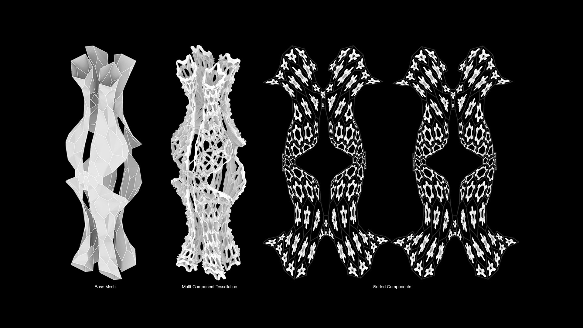
2. Prepare Components
create loose parts
The prepare components section provides the tools necessary to break a tessellation into multiple parts and then reorient each part into the 2D layout that was previously created. To use these functionalities make sure a 2D layout has been created using the Prepare Base functionalities.
Use the Create Loose Parts button to break down the tessellation so that each part is its own object within Blender. For quick selection, the parts have been placed in a new collection.
Sort components
The Sort Components button then reorients all selected parts from their 3D position to the newly created 2D layout, maintaining their general orientation but repositioning to be as flat as possible on the 2D layout.
The individual parts are also renamed based on the sort faces naming convention.
3.UTILS
edge naming
The Utils section includes functionalities to name the edges, change face and edge text size, change the line weight thickness of the MST, and select individual components by their number.
The Edge Naming adds text to each of the edges on the 2D layout to help with the orientation of parts. It currently serves as a reference while assembling although future updates may include ways to add this information to the part geometry itself. You can change the text size using the Edge Text Size input parameter.
To use Edge Naming you must select the 2D layout. If the text does not appear, check that the size is not too small.
select component
The Select Component button was added to help during the assembly process. It allows users to quickly find a part within the layout to reference it’s position and orientation during assembly. Useful in finding where a piece goes in multipart assemblies with many parts.
To use this function, type in the number of the part and click on select. It will make the part the active object within the Blender viewport.
4. animate transition
transition value & Keyframe transform
The tools in the animate transition section allows you to animate the repositioning of the parts from the 3D position to the 2D layout.
Changing between 0 and 1 in the Transition Value allows you to go from the 3D position (Value of 0) to the 2D layout position (Value of 1) for the selected part. You can move parts individually or select all the parts to move them together.
To animate you need to use keyframes. Use Keyframe Transform to set the keyframe at different points in the timeline.